







Table of Contents
Why Does Pneumatic Conveying System Design Matter So Much?
A pneumatic conveying system that is undersized for its application will block repeatedly, reduce plant throughput, and require constant attention from maintenance teams. A system that is oversized wastes energy and can cause particle degradation from excessive velocity. The design must be matched precisely to the material being conveyed, the required tonnage, the pipeline geometry, and the physical layout of the plant.
Unlike mechanical conveying systems, which are relatively forgiving of modest over or undersizing, a pneumatic conveying system operates within defined velocity windows. Below the minimum transport velocity, material settles out of suspension and blocks the pipe. Above the optimum velocity, energy consumption rises steeply and material attrition increases. Getting the design right is not optional.
Step 1: Define the Material Properties
The starting point for any pneumatic conveying system design is a complete understanding of the material to be conveyed. The following properties must be known before any engineering calculation begins:
- **Bulk density** in kilograms per cubic metre, both loose poured and aerated, since both values affect conveying behaviour differently
- **Particle size and size distribution** as the minimum and maximum particle diameter, and the d50 and d90 values from a particle size analysis
- **Particle shape**, whether spherical, angular, fibrous, or irregular, as this affects pick up velocity and bend wear significantly
- **Abrasiveness** rated on the Mohs scale or by standard abrasion tests, since abrasive materials require hardened or lined pipeline and bends
- **Hygroscopicity** and moisture content, as wet or moisture absorbing materials can cake on pipe walls and block the system
- **Friability** and fragility, since delicate particles require dense phase mode or carefully controlled velocity in dilute phase
- **Explosivity and flammability**, as combustible powders require earthed pipelines, explosion venting, and in some cases nitrogen blanketing
Step 2: Determine Conveying Mode and Minimum Transport Velocity
Based on the material properties established above, the conveying mode is selected. For robust free flowing materials, dilute phase conveying is appropriate. The minimum conveying velocity for dilute phase transport depends on particle size and density. A commonly used reference value is:
Minimum transport velocity = K x square root of (particle density x particle diameter)
where K is an empirical constant that depends on pipe orientation, particle shape, and system configuration. In practice, design velocities are set 20 to 30 percent above the minimum pick up velocity to ensure reliable operation across the full range of material conditions. For most bulk solids in dilute phase conveying, design velocities fall between 18 and 28 metres per second.
For dense phase conveying, the conveying velocity is set by the slug formation characteristics of the specific material and is typically between 2 and 8 metres per second.
Step 3: Select Pipeline Bore
The pipeline bore is calculated from the required volumetric air flow and the design conveying velocity using the continuity equation:
Pipe cross sectional area = Volumetric air flow rate divided by conveying velocity
From this area, the internal diameter is calculated and the nearest standard pipe bore is selected. The volumetric air flow required depends on both the air velocity and the mass flow rate of material. For dilute phase systems, the solid loading ratio (mass flow of material divided by mass flow of air) is typically between 3 and 15.
Standard pipe bore selection is also influenced by the nature of the material. Fine powders with tendency to compact or cake should be conveyed in slightly larger bore pipes to allow bypass air flow around any incipient block. Abrasive materials should be conveyed in Schedule 40 or heavier pipe to provide a safe wear allowance.
Step 4: Calculate System Pressure Drop
Total pressure drop across the pneumatic conveying system is the sum of:
- Pressure drop to accelerate material from rest to conveying velocity at the pickup point
- Friction pressure drop in straight horizontal pipe runs
- Pressure drop through each vertical section, both upward and downward
- Pressure drop through each bend
- Pressure drop through the separation equipment at the destination
- Additional safety margin, typically 15 to 20 percent
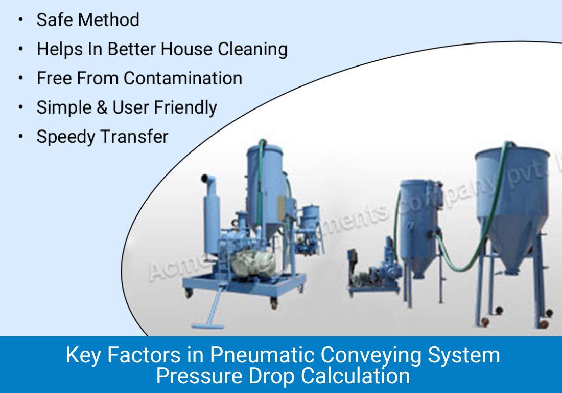
The total pressure drop determines the operating pressure at the blower or compressor discharge, which in turn determines the machine selection. For dilute phase systems, pressure drops of 0.3 to 0.8 bar are typical. For dense phase systems, 1.5 to 4.5 bar is the normal range.
Our Other Product
Step 5: Design the Bends Correctly
Bends are the most wear prone component in any pneumatic conveying system and the most common location for pipeline failures. They also impose the highest local pressure drop. The following principles govern bend design:
- **Long radius bends** with a radius to diameter ratio of 6 or greater dramatically reduce wear compared to short radius elbows. Acme recommends minimum R/D of 8 for mildly abrasive materials and 12 or greater for highly abrasive materials
- **Blind tee bends** use a closed pocket at the corner where material accumulates and forms its own cushion against the wall. They are very effective for abrasive materials but impose slightly higher pressure drops than smooth radius bends
- **Ceramic lined bends** or hardened steel bends with wear resistant alloy inserts should be specified for materials above a Mohs hardness of 4
- **Bend spacing** matters as much as bend design. Material re accelerates to full velocity after each bend over a distance of 10 to 20 pipe diameters. Bends placed too close together leave material partially decelerated entering the next bend, which sharply increases wear
- **Vertical to horizontal transitions** at the bottom of downcomer sections are particularly susceptible to wear and should always use long radius bends with wear protection
Step 6: Specify the Air Source
The air source is selected on the basis of the calculated volumetric flow in cubic metres per hour at the operating pressure. Acme Air Equipments manufactures two types of motive air equipment for pneumatic conveying systems:
Twin lobe and tri lobe roots blowers are the standard choice for dilute phase systems requiring pressures up to 1.0 bar gauge. Acme’s blower range covers flows from 100 to 18,000 cubic metres per hour. The positive displacement characteristic of a roots blower means it delivers constant flow regardless of modest pressure variation, which gives good conveying stability.
Rotary compressors in the twin lobe and tri lobe configuration cover the range from 1.0 to 3.0 bar gauge and are used for higher pressure dilute phase systems and for dense phase conveying at moderate pressures. Acme’s rotary compressor range is available in both air cooled and water cooled versions.
Step 7: Size the Separator and Filter
The separator at the destination must handle the full air and material flow without significant material carryover into the exhaust air. For most applications, a pulse jet bag filter is used, with the filter area calculated using an air to cloth ratio appropriate for the material. For coarse granular materials, air to cloth ratios of 2 to 4 metres per minute are standard. For fine powders below 10 microns, ratios of 0.8 to 1.5 metres per minute are used to avoid premature filter blinding.
The compressed air supply for the pulse jet cleaning mechanism must also be specified. Pulse cleaning pressure of 5.5 to 7 bar is standard. Acme supplies complete filter systems including the pulse valves, solenoid panel, and compressed air header as part of its turnkey pneumatic conveying system packages.
Frequently Asked Questions
Pneumatic Conveying System Design: How to Size Pipeline, Bends, and Air Supply for Your Application
What is the minimum velocity required for dilute phase pneumatic conveying?
For most bulk solids, the minimum transport velocity in dilute phase conveying ranges from 15 to 20 metres per second in horizontal pipelines. Design velocities are set 20 to 30 percent above this minimum to ensure reliable operation. Very heavy materials such as metal powders require higher velocities, while very light materials such as expanded polystyrene beads may be conveyed at lower velocities.
How many bends can a pneumatic conveying system have?
There is no fixed maximum, but each bend adds to the system pressure drop and each bend is a potential wear point. As a practical guideline, dilute phase systems should not exceed 8 to 10 bends in a single pipeline run without careful pressure drop budgeting. If the layout demands more bends, the pipe bore or operating pressure should be increased to accommodate the additional resistance.
What pipe material is recommended for pneumatic conveying of abrasive materials?
Standard mild steel Schedule 40 pipe is acceptable for mildly abrasive materials with Mohs hardness below 3. For more abrasive materials, hardened steel pipe with a minimum wall thickness of 6 millimetres is recommended. For highly abrasive materials such as alumina, silicon carbide, or coal, ceramic lined pipe or basalt lined pipe sections should be used at critical high velocity zones.
How is the roots blower sized for a pneumatic conveying system?
The roots blower or rotary compressor is sized based on the calculated volumetric air flow at the operating pressure. The key inputs are the pipe cross sectional area, the design conveying velocity, and the pressure at the blower discharge. A derating factor for temperature and altitude is applied, and the nearest standard blower frame size from Acme's range is selected. Acme provides performance curves for each blower model to confirm the operating point.

CEO
Mr. Vishwesh Pardeshi is the CEO of Acme Air Equipments Company Pvt. Ltd., an industrial and engineering goods manufacturing company based in Ahmedabad, Gujarat (India). He has taken over the responsibility from founding Partners and Directors of the Company, and is now leading a talented group of professionals since 2020 by bringing in vast industrial and management expertise. By qualification, he holds a Bachelor Degree in Mechanical Engineering and also holds a MBA degree from reputed institutes. Under his leadership, the Company has successfully executed prestigious projects by delivering high quality and world class products from a state of the art manufacturing facility which combines CNC-enabled precision manufacturing and strong after sales support. In line with the Vision, Mission and Core Values of the Organization, Mr. Vishwesh Pardeshi continues to drive Quality, Reliability and Global Expansion at Acme Air Equipments Co. Pvt. Ltd.