






Table of Contents
Problem 1: Pipeline Blockage
A pipeline blockage is the most disruptive failure in a pneumatic conveying system and the one most frequently encountered. The conveying air continues to flow but material stops moving, pressure at the blower or compressor discharge rises steeply, and throughput falls to zero.
Common causes of pipeline blockage
- Air velocity has dropped below the minimum transport velocity due to a worn blower impeller, an air leak in the pipeline, or a blocked air inlet filter
- Material moisture content has increased, causing the powder to cake on the pipe wall and progressively narrow the bore
- A piece of tramp material or a lumped agglomerate has partially blocked a bend or valve, with finer material then packing behind it
- System pressure demand has exceeded the available blower pressure due to a pipeline modification or a higher material loading than designed
Troubleshooting and fix
Measure blower discharge pressure and compare with the design specification. If pressure is low, check the inlet air filter for blinding, check shaft seal condition, and check that no air valves are partially closed. If pressure is correct but the block persists, isolate and pressurise each pipe section to locate the blockage point. Introduce compressed air into the line ahead of the blockage or use a rodding tool to break up the packed material. Review the material moisture content and check the seal water source if applicable.
Problem 2: Elevated System Pressure Drop
A gradual increase in operating pressure over days or weeks, without a corresponding increase in throughput, indicates a progressive restriction in the system.
Common causes
- Bag filter bags are blinding due to inadequate pulse jet cleaning, high moisture in the cleaning air, or bags that are beyond their service life
- Material is building up at bends due to velocity below pick up threshold or a material with cohesive properties
- A rotary valve or slide valve is not opening fully due to wear on the rotor or a foreign object trapped between rotor and housing
Troubleshooting and fix
Check the differential pressure across the bag filter. A reading above 200 millimetres water gauge on a properly cleaned filter indicates filter blinding. Check pulse valve solenoid coils and diaphragm condition, and verify that cleaning air pressure at the filter header is between 5.5 and 7 bar. If the filter is satisfactory, isolate sections of pipe to identify the restriction point using a portable pressure gauge.
Problem 3: Material Degradation
When fragile materials are being conveyed and particle size analysis at the destination shows more fines than at the origin, the conveying velocity is too high or the bend design is causing impact damage.
Common causes
- Air velocity significantly above the minimum transport velocity, which is a common consequence of oversized blower selection
- Short radius elbows or standard tee bends causing high impact velocity at bend corners
- Pneumatic conveying of inherently fragile material in dilute phase mode when dense phase would be more appropriate
Troubleshooting and fix
Measure actual conveying velocity using a pitot tube and compare with the design velocity. If the system is running significantly above the design point, reduce blower speed using a variable speed drive or by installing an inlet throttle valve. Replace short radius bends with long radius swept bends or blind tee bends depending on the material. For materials that are inherently fragile, consult Acme on whether the system can be converted to dense phase mode.
Problem 4: Air Leaks
Air leaks reduce the volume of air available for conveying, drop the pipeline velocity, and can cause partial or complete blockage. They also waste energy continuously.
Common causes
- Worn shaft seals on rotary valves at material entry or exit points
- Flange gasket failures on pipeline joints, particularly in high temperature or high vibration locations
- Cracked pipeline at worn bends or at welded connections that have experienced fatigue
Troubleshooting and fix
Apply soapy water to all flanged joints and rotary valve shaft areas while the system is operating and look for bubbles. Any leaking flange should be re tightened or re gasketed. Rotary valve shaft seals should be inspected and replaced according to the manufacturer’s schedule. Acme Air Equipments supplies replacement seals and rotary valve rotors for all models in its range.
Problem 5: Separator Carryover
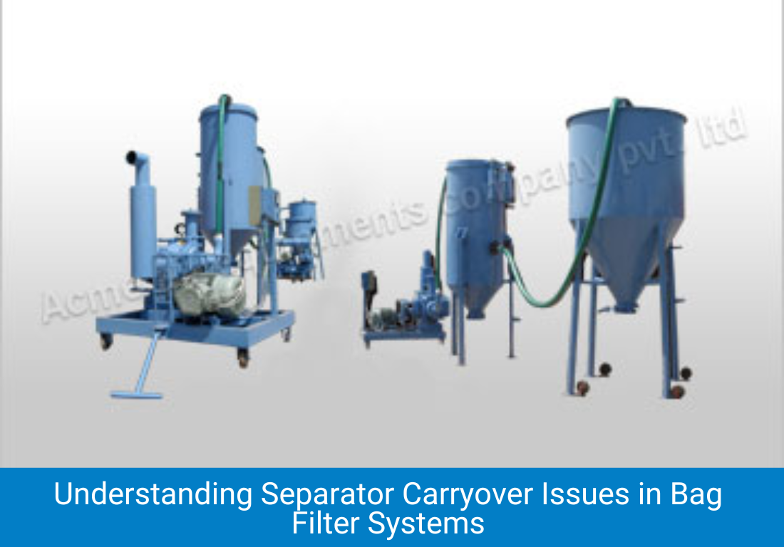
Material appearing in the exhaust air or in the area around the bag filter outlet is separator carryover, and it represents both a product loss and a potential dust hazard.
Common causes
- Torn or incorrectly fitted filter bags allowing material to bypass the filter medium
- Pulse jet cleaning mechanism failure, leading to progressive bag blinding followed by sudden breakthrough as pressure differential peaks
- Filter bag material not suitable for the particle size, with fine particles passing through a coarser weave
Troubleshooting and fix
Inspect filter bags by temporarily placing a sheet of white paper in the clean air chamber on the outlet side while the system is running. Product on the paper indicates bag failure. Remove and inspect all bags, replacing any that show holes, unsealed seams, or deteriorated fabric. Verify that the pulse valve timing cycle is functioning on all solenoids.
Problem 6: High Blower or Compressor Temperature
Excessive discharge temperature from the roots blower or rotary compressor protecting the system indicates either overloading or cooling system failure.
Common causes
- System back pressure higher than the blower design rating, which increases internal slippage and thermally loads the machine
- Cooling air inlet to an air cooled machine is blocked by dust accumulation on the cooling fins
- Low oil level in the gear casing, allowing gear and bearing temperatures to rise
Troubleshooting and fix
Check blower discharge pressure against the machine nameplate rating. If system pressure is within limits, clean the cooling fins thoroughly and check the oil level in the gear housing. For water cooled machines, check cooling water flow rate and temperature. Acme provides recommended oil grades and oil change intervals in its blower and compressor operation manuals.
Our Other Product
Problem 7: Velocity Fluctuation and Pulsing
Irregular flow, visible as rhythmic pulsing of material at the destination rather than steady flow, indicates instability in the air supply or in the material feed.
Common causes
- Variable material feed rate from a poorly adjusted rotary valve or venturi nozzle at the pickup point
- Air receiver is too small, allowing pressure to fluctuate with blower cycle rather than smoothing it
- For dense phase systems, the pressure vessel venting cycle is not properly synchronised with the fill and convey cycles
Troubleshooting and fix
For dilute phase systems, verify that the rotary valve feeder speed is set correctly and that the rotor clearances are within specification. An undersized air receiver should be replaced with one of at least 5 times the blower swept volume per revolution. For dense phase pressure vessel systems, review the programmable logic controller cycle timings with Acme’s commissioning team.

Problem 8: Premature Bend Wear
Rapid wear at bends, visible as wall thinning, external surface roughening, or complete perforation at the outer radius, indicates a velocity or material specification mismatch.
Common causes
- Material Mohs hardness higher than anticipated at design stage, causing faster abrasion than the bend material can withstand
- Conveying velocity above the design point, which increases the impact energy of particles at the bend wall according to a power law relationship
- Use of standard short radius elbows instead of long radius sweep bends
Troubleshooting and fix
Replace failed bends with long radius swept bends of at least R/D ratio 8 in mild steel, or with ceramic lined bends for abrasive materials above Mohs 4. Reduce conveying velocity if possible. Apply ultrasonic thickness gauging to other bends in the system to predict remaining life before the next failure occurs.
Frequently Asked Questions
Common Problems in Pneumatic Conveying Systems and How to Troubleshoot Them
Why does my pneumatic conveying system keep blocking even though the blower is running?
The most likely cause is that the conveying velocity has fallen below the minimum transport velocity. This happens when the air inlet filter is partially blocked, when there is an air leak in the pipeline, or when the blower or compressor impeller has worn and is delivering less flow than rated. Check blower discharge pressure and compare with the design specification. Also verify that the material moisture content has not increased, as damp material requires higher velocity to convey reliably.
How often should bag filters in a pneumatic conveying system be replaced?
Filter bag life depends on material abrasiveness, particle size, and pulse cleaning frequency. As a general guideline, filter bags in well maintained pneumatic conveying systems handling non abrasive powders last 2 to 4 years. For abrasive materials or high temperature applications, life may be shorter. The best indicator is the differential pressure trend. If differential pressure rises progressively despite correct pulse cleaning, bag replacement should be planned.
Can a pneumatic conveying system be converted from dilute phase to dense phase?
Conversion is possible in principle but requires a thorough review of the existing pipeline, air supply, and separator. Dense phase operation requires higher pressure air supply, different pipeline bore sizing, pressure vessels and level sensors at the pickup points, and modified control logic. Acme Air Equipments can evaluate an existing system and advise on the feasibility and cost of conversion.
CEO
Mr. Vishwesh Pardeshi is the CEO of Acme Air Equipments Company Pvt. Ltd., an industrial and engineering goods manufacturing company based in Ahmedabad, Gujarat (India). He has taken over the responsibility from founding Partners and Directors of the Company, and is now leading a talented group of professionals since 2020 by bringing in vast industrial and management expertise. By qualification, he holds a Bachelor Degree in Mechanical Engineering and also holds a MBA degree from reputed institutes. Under his leadership, the Company has successfully executed prestigious projects by delivering high quality and world class products from a state of the art manufacturing facility which combines CNC-enabled precision manufacturing and strong after sales support. In line with the Vision, Mission and Core Values of the Organization, Mr. Vishwesh Pardeshi continues to drive Quality, Reliability and Global Expansion at Acme Air Equipments Co. Pvt. Ltd.